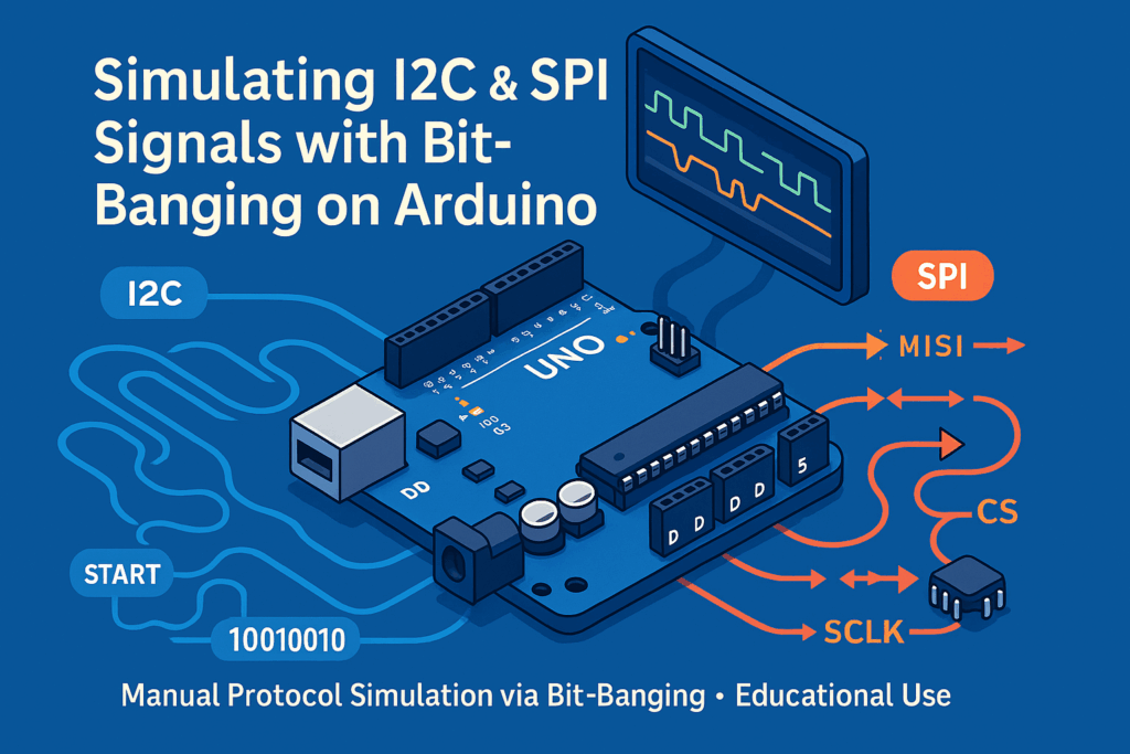
In this post, we explore how to manually simulate I2C and SPI signals using an Arduino and simple digital I/O operations — a method often called bit-banging. This can be useful for debugging, testing logic analyzers – my case -, or understanding how these communication protocols work under the hood.
Inhalt
Overview of I2C and SPI
I2C (Inter-Integrated Circuit)
I2C is a synchronous, multi-master, multi-slave, packet-switched, single-ended, serial communication bus. It typically uses:
- SCL (Clock): Controls the timing of communication
- SDA (Data): Transfers data bit-by-bit
I2C communication consists of start/stop conditions, address and data transmission, and acknowledgements.
SPI (Serial Peripheral Interface)
SPI is another synchronous communication protocol but faster and more flexible than I2C. It uses:
- MOSI (Master Out, Slave In): Data from master to slave
- MISO (Master In, Slave Out): Data from slave to master
- SCLK: Clock line for synchronization
- CS (Chip Select): Activates the specific slave
The Arduino Script: What It Does
The provided Arduino script simulates both I2C and SPI traffic by toggling GPIO pins manually. This is a great way to learn how these protocols operate at a low level.
Pin Configuration
| Function | Pin |
|---|---|
| I2C SCL | D0 (GPIO 0) |
| I2C SDA | D1 (GPIO 1) |
| SPI MOSI | D2 (GPIO 2) |
| SPI MISO | D3 (GPIO 3) |
| SPI SCLK | D4 (GPIO 4) |
| SPI CS | D5 (GPIO 5) |
I2C Simulation
The script implements the I2C protocol manually:
- Sends a START condition by pulling SDA low while SCL is high.
- Transmits 8 bits of data, starting from the most significant bit (MSB).
- Sends a simulated ACK bit (we don’t read a real response in this case).
- Ends the transmission with a STOP condition.
SPI Simulation
For SPI, the script:
- Pulls CS low to select the slave.
- Sends 8 bits of data via MOSI, toggling SCLK with each bit.
- Pulls CS high to finish the transfer.
What This Is Useful For
- Learning how serial protocols work.
- Testing external analyzers or microcontrollers‘ input behavior.
- Understanding timing and signaling for embedded development.
#include <Arduino.h>

// --- I2C Pins ---
#define I2C_SCL 0  // D0
#define I2C_SDA 1  // D1

// --- SPI Pins ---
#define SPI_MOSI 2 // D2
#define SPI_MISO 3 // D3 (optional in this simulation)
#define SPI_SCLK 4 // D4
#define SPI_CS   5 // D5

// I2C timing
#define I2C_FREQ 100000
#define I2C_DELAY_US (1000000 / I2C_FREQ) / 2

// SPI timing
#define SPI_DELAY_US 10

void i2c_start() {
  digitalWrite(I2C_SDA, HIGH);
  digitalWrite(I2C_SCL, HIGH);
  delayMicroseconds(I2C_DELAY_US);
  digitalWrite(I2C_SDA, LOW);
  delayMicroseconds(I2C_DELAY_US);
  digitalWrite(I2C_SCL, LOW);
}

void i2c_stop() {
  digitalWrite(I2C_SDA, LOW);
  digitalWrite(I2C_SCL, HIGH);
  delayMicroseconds(I2C_DELAY_US);
  digitalWrite(I2C_SDA, HIGH);
  delayMicroseconds(I2C_DELAY_US);
}

void i2c_write_byte(uint8_t byte) {
  for (int i = 0; i < 8; i++) {
    digitalWrite(I2C_SDA, (byte & 0x80) ? HIGH : LOW);
    delayMicroseconds(I2C_DELAY_US);
    digitalWrite(I2C_SCL, HIGH);
    delayMicroseconds(I2C_DELAY_US);
    digitalWrite(I2C_SCL, LOW);
    byte <<= 1;
  }

  // ACK bit (just simulate low)
  pinMode(I2C_SDA, INPUT); // Let the line float (simulate read)
  digitalWrite(I2C_SCL, HIGH);
  delayMicroseconds(I2C_DELAY_US);
  digitalWrite(I2C_SCL, LOW);
  pinMode(I2C_SDA, OUTPUT);
}

void spi_transfer_byte(uint8_t byte) {
  digitalWrite(SPI_CS, LOW);
  for (int i = 0; i < 8; i++) {
    digitalWrite(SPI_MOSI, (byte & 0x80) ? HIGH : LOW);
    delayMicroseconds(SPI_DELAY_US);
    digitalWrite(SPI_SCLK, HIGH);
    delayMicroseconds(SPI_DELAY_US);
    digitalWrite(SPI_SCLK, LOW);
    byte <<= 1;
  }
  digitalWrite(SPI_CS, HIGH);
}

void setup() {
  Serial.begin(115200);
  Serial.println("Simulating I2C and SPI signals...");

  // I2C
  pinMode(I2C_SCL, OUTPUT);
  pinMode(I2C_SDA, OUTPUT);
  digitalWrite(I2C_SCL, HIGH);
  digitalWrite(I2C_SDA, HIGH);

  // SPI
  pinMode(SPI_MOSI, OUTPUT);
  pinMode(SPI_MISO, INPUT); // not used
  pinMode(SPI_SCLK, OUTPUT);
  pinMode(SPI_CS, OUTPUT);
  digitalWrite(SPI_CS, HIGH);
  digitalWrite(SPI_SCLK, LOW);
}

void loop() {
  // --- Simulate I2C: Send one byte ---
  i2c_start();
  i2c_write_byte(0xA5); // example byte (0b10100101)
  i2c_stop();

  // --- Simulate SPI: Send one byte ---
  spi_transfer_byte(0x3C); // example byte (0b111100)

  delay(50); // Wait some time
}